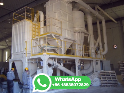
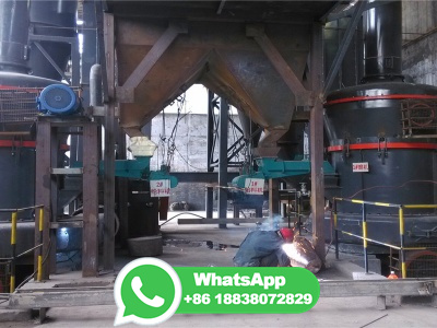
sbm/sbm autogenous mill at main · redmik40/sbm
WEBFind and fix vulnerabilities Codespaces. Instant dev environments

WEBFind and fix vulnerabilities Codespaces. Instant dev environments

WEBJun 24, 2015 · Grate Discharge Ball Mills have shown 25% to 45% more tonnage ground and a substantial reduction in power consumed per ton of material compared size for size with overflow mills. To illustrate the characteristics of various type mills we have shown the types of discharge for rod mills and ball mills. There are essentially four types of rod .

WEBMay 9, 2019 · Measuring ball mill ventilation. Share. May 09, 2019. by GCP Applied Technologies Mill ventilation is important for cooling the mill, removing moisture and improving mill efficiency. Typically, a velocity across the media of 1m/s is a good target. ... Depending on the mill configuration, this can be anywhere from 25 additional air .

WEBOf course, even if we set a more appropriate cement fineness, it is difficult to change the current situation that the flow velocity in the opencircuit ball mill is only 1/21/3 of that in the closedcircuit ball mill with the same specifiion, which will lead to poor comprehensive performance of finished cement, low system output and ...

WEBBall Mill Pulverizer Air/Coal Flow Diagram RAW COAL IN RAW COAL IN AIR IN AIR IN AIR / PULVERIZED COAL OUT AIR . diagram of stone crushing plant – Process Crusher, Mining . schematic diagram stone crushing plant works – . ball mill, sand making machine, and all kinds of mining machinery and equipment, .

WEBDesign of an automated grinding media charging system for ball mills ... Figure 5: Ladder Flow Diagram OPC COMMUNICATION LINK An OPC Server must be used to establish the link between the JADE program and the PLC program. The OPC should solve the following challenges in the charging system designed: A constant value (, a .

WEBJun 1, 1999 · The grinding circuit ( Fig. 1) used for the present study is part of a copper concentrator plant. The system consists of a ball mill, hydrocyclones, pulp sump and associated pumps and solids feeding conveyors. The feed, copper ore (from primary crusher, size 3 in) is fed into the ball mill by vibratory conveyors.

WEBDownload scientific diagram | Ball mill flow diagram (ball mill inlet pulp = hydrocyclone UF + water) from publiion: MATERIAL BALANCE IN FROTH FLOTATION USING MICROSOFT EXCEL SOLVER | This ...

WEBSep 1, 2007 · Responses of mill solids concentration to step disturbance in the manipulated variables: (1) feed rate positive change + t/h, (2) mill feed water flow rate positive change + m 3 /h, (3) sump dilution water flow rate positive change + m 3 /h and (4) pump speed negative change − Hz. Download : Download fullsize image; Fig. 4.

WEBApr 23, 2023 · The energy con sumption for spherical balls was Kw after grinding for 420 minutes, producing a 45µm. residue of % whilst that of cylpebs was after grinding for 295 minutes producin ...

WEBApr 1, 2013 · Closed circuit milling flowsheet. The total solids mass flow of the mill discharge is: (2) Q + CQ = Q ( 1 + C) The final product mass flow in the mill discharge is Q / E and the amount of final product in the circulating load is: (3) Q E Q = Q 1 E 1. The mass flow of the coarse material in the mill discharge is the difference between the ...

WEBDownload scientific diagram | Schematic Flow Sheet of the AG/SAG Mill Model. ... An example of research focused on ball mills is the work of Katubilwa and Moys regarding the effect of ball size ...

WEBJan 10, 2016 · On a 11'6" x 22'0" Ball Mill, the trunnion bearing lubriion system provides continuous low pressure flood oil for cooling and lubriion of the bearings, and high pressure oil for hydrostatic lift of the feed and discharge trunnions during startup of the mill. System monitors including pressure switches and flow monitors are ...

WEBJun 7, 2023 · Mathematical validation and comparison of coal milling operations of a horizontal ball tube mill and a vertical bowl mill loed in two distinct coal based power plants in India was carried out. The coal mill model was developed and the unknown model coefficients were obtained numerically by genetic algorithm (GA). The input variables of .
![Flow Control Valves: Diagram, Types, Working Uses [PDF]](/9h6ub17/253.jpg)
WEBNov 5, 2022 · In hydraulics, flow control valves are used to control the amount of oil supplied to various parts within a hydraulic system. In this way, the momentum of a cylinder or the rotational speed of a hydraulic motor can be controlled. However, a basic flow control valve has an opening that can be changed to increase or decrease the flow rate.

WEBSep 17, 2017 · A schematic flow diagram of palm oil mill outlines the entire process from beginning to end. Palm oil is extracted from the palm fruits and then processed into a variety of consumable products. The schematic flow diagram of palm oil mill begins with the collection of ripe fresh palm fruit bunches. The bunch is weighed and then transported to ...

WEBJan 1, 2016 · The general principle behind the structure of the volume is that of flow sheeting based on unit operations and applied to a mineralogical classifiion of gold ore types. ... Flexibility to return SAG feed an option to balance SAG and ballmill circuits during periods of ballmill limitations: 17: Louvicourt: Quebec: Comminution, flash flotation:

WEBJan 1, 2016 · Ball mills are displaced, based on a lack of need, in singlestage AG/SAG plants. Ballmill technology is well understood, as is classifiion, which is typically performed in hydrocyclones. However, in practice, secondary milling circuits are often operated at less than peak efficiency. With throughput in many cases worth more .

WEBFeb 1, 2021 · Comparing to the widely applied ball milling, the second law efficiency is % higher for the VRM than the ball mill. ... the energy flow diagram (Sankey diagram), and the exergy flow diagram (Grassmann diagram) of the VRM are illustrated on where the energy and exergy are lost in the system and give useful insights for .

WEBOct 19, 2016 · Ball Mill Sole Plate. This crown should be between .002″ and . 003″, per foot of length of sole plate. For example, if the sole plate is about 8′ long, the crown should be between .016″ and .024″. Ball Mill Sole Plate. After all shimming is completed, the sole plate and bases should be grouted in position.

WEBDownload scientific diagram | Schematic diagram of a ball mill. The balls make up the grinding media and drive rollers help to rotate the milling chamber. from publiion: Overview of milling ...

WEBIn this research, the effect of ball size distribution on the mill power draw, charge motion regime and breakage mechanism in a laboratory ball mill was studied using the discrete element method ...

WEBAug 12, 2021 · Furthermore, ball milling technique coupled with chemical and physicochemical pretreatments has been shown to facilitate lignin removal, reduce cellulose crystallinity, and increase the specific surface area which ultimately improves the digestibility of lignocellulosic biomass. ... Figure 4 illustrates the process flow diagram .

WEBDec 2, 2016 · Modifiions to the SABC comminution circuit included an increase in the SAG mill ball charge from 8% to 10% v / v; an increase in the mill ball charge from 23% v / v to 27% v / v; an increase in the maximum operating power draw in the ball mill to 5800 kW; the replacement of the HP Series pebble crusher with a TC84 crusher; and the .

WEBDischarge of pebbles, finer rock, ball ss and slurry from mills and its flow through trommels, and into other processing operations has strong impacts on overflow ball mill performance.

WEBA schematic diagram of a tubular ball mill. The balls compose the milling elements and drive rollers help to rotate the milling chamber. Adapted from Loh et al. [12] . Source publiion.

WEBMar 20, 2013 · attrition mill diagram. The fiber is then taken out using an attritionimpact mill. The fiber is used as a major element in animals feeds. .. Get price and support, find the working site in your country ! Please enter your demand such as production capacity, feeding material size, final product size.

WEBApr 30, 2023 · Ball mill is a type of grinding equipment that uses the rotary cylinder to bring the grinding medium and materials to a certain height and make them squeeze, impact, and grind and peel each other to grind materials. Ball mill is the key equipment for crushing materials after they are crushed. It is widely used in cement, silie products, new ...

WEBDownload scientific diagram | Ball mill steady state simulation with 35% filling modelled as a (a) 2D simulation using N=6744 particles, (b) 10% slice of the length using N=385 534 particles and ...

WEBAug 10, 2013 · Process flow diagram pg Download as a PDF or view online for free ... Diagram Balok Proses PembuatanDiagram Balok Proses Pembuatan Pupuk SP36Pupuk SP36 BATUAN FOSFAT BALL MILL CONE MIXER GRANULATOR DRYER SCREEN COOLER PRODUK SP36/TSP ASAM FOSFAT SCRUBBING Over Size Under Size On .

WEBThe required speed of the ball mill with grinding media with innovative lifters at aract mode of operation for the three types of materials is almost the same with an average value of 45% of CS.

WEBApr 1, 2014 · The air flow system of a Tubeball mill can be described by the diagram in Fig. 2, in which 7A, 8A and 14A are inlet air dampers while 12A1 and 12A2 are exhaust outlet dampers. ... The block diagram for online mill condition monitoring system is shown in Fig. 12. The mill model is running in parallel with the power plant coal mill operation ...

WEBFigure 1 presents the design of the clinker grinding system (closed circuit), which consists of a twochamber ball mill and the separator (Plasari and T heraska, 19 81). Cement clinker is usually ...